SYMBOL DEFINITIONS
The Symbol Definition Point Notation
Before delving into the actual XML structure, it is important that users familiarize themselves with the Symbol Definition Point notation, since it is used throughout the document.
The symbol definition point notation defines a point consisting of an X and a Y value. The X value denotes a point along the horizontal axis, while the Y value denotes a point on the vertical axis. A point may be used as an
absolute value, which is interpreted at rendering time as relative to the top-left corner of the canvas. Alternatively, a point may be relative to the current position of the pen, in this case a negative X value means that the
point lies to the left of the pen position while a positive X value means the point lies to the right of the pen position. Similarly, a negative Y value indicates that the point lies above the pen position, while a positive Y
value means the point lies below the pen position.
The point notation is written as follows: X@Y. If the value of X is -10, and the value of Y is 34, the point will be written as -10@34. The X and Y values may also be fractions. For example, a point with an X value of 1.25 and a
Y value of -12.33 will be written as 1.25@-12.33.
The X and Y values may also be written as Smalltalk statements, provided the answer is numeric. These Smalltalk statements will be executed at rendering time. The statement "10 + 3 – 14 @ 25 * 2" will resolve to "-1@50"
when the symbol is rendered.
Because the content of the XML needs to be encoded, all PLUS symbols should be written as "%2B". The previous example would therefore be written as "10 %2B 3 – 14 @ 25 * 2". Fortunately, most other mathematical symbols can
stay the same and still be valid inside an XML tag.
When the Smalltalk statements describing point values are compiled, the values of the canvas' WIDTH, HEIGHT, TOP, BOTTOM, LEFT and RIGHT properties are passed into the statements as arguments. Using these keywords in the
statements will therefore result in valid Smalltalk as well. For example, given a canvas with a WIDTH of 10 and a HEIGHT of 50, the statement "WIDTH * 2 @ HEIGHT / 2" will resolve to "20@25".

Structure of the Symbol Definition Script
The XML notation for EVA Netmodeler Symbol Definitions consists of four basic parts, viz. The Canvas, Annotation, Pen Definition and the Pen Command sections. The basic structure of the XML is as follows:
<SYMBOLDEFINITION>
<CANVAS>
…Canvas Commands…
</CANVAS>
<ANNOTATION>
…Annotation Commands…
</ANNOTATION>
<PENDEFINITION>
…Pen Definition Commands…
</PENDEFINITION>
…Pen Commands…
</SYMBOLDEFINITION>
Canvas Section
In this section, the properties describing the canvas on which the symbol will be drawn are specified. These properties describe the dimensions (i.e. Height and Width) of the canvas, as well as the background and border colors.
Annotation Section
This section is used to specify the annotation properties for the symbol. The annotation type (e.g. "ITEMNAME" or "ICON"), the position of the annotation relative to the canvas and the dimensions of the annotation are specified here. This section is optional. If it is omitted this simply means that no annotations will appear when the symbol is rendered.
Pen Definition Section
A symbol may be drawn using multiple pens that vary in color, type of pen and line width, amongst other things. In this
section, different pens are created and their properties defined. Every pen should be given a name unique to the Symbol Definition script. This name is used to refer to the particular pen in the "Pen Command" section.
Pen Command Section
This section contains a series of pen commands. This is where the actual drawing of the symbol takes place. In this section pens can be activated, the state of the pen can be set and the pen can be moved around on the canvas.
Structure of the Canvas Section
This section defines the background canvas on which the symbol will be rendered, the following keyword commands are used to specify the canvas properties;
Keyword Command
|
Description
|
Valid Values
|
WIDTH
|
The width of the canvas (in inches)
|
Any integer or fraction (e.g. 1, 2.5, 3.25 etc.)
|
HEIGHT
|
The height of the canvas (in inches)
|
Any integer or fraction (e.g. 1, 2.5, 3.25 etc.)
|
BACKCOLOR
|
The background color of the canvas
|
Web-like HTML RGB value (e.g. 000000 for Black or FFFFFF for White)
|
BACKALPHA
|
This command sets the transparency of the canvas. A value of 0 means that it is totally transparent; while a value of 1 means that it is totally opaque.
|
Integer 1 or any fraction less than 1, e.g. 0.987
|
BORDERCOLOR
|
The color of the canvas border
|
Web-like HTML RGB value (e.g. 000000 for Black or FFFFFF for White)
|
BORDERWIDTH
|
The width, in pixels, of the canvas border
|
Any integer greater than or equal to 0
|
BORDERALPHA
|
The transparency of the canvas border, functions the same as BACKALPHA
|
Integer 1 or any fraction less than 1, e.g. 0.987
|
Canvas Examples
The following table shows sample canvas XML definitions and how they are rendered in EVA Netmodeler Graphical Modeler
Example XML
|
Canvas rendered in
EVA Netmodeler Graphical Modeler
|
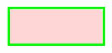
<SYMBOLDEFINITION>
<CANVAS>
<WIDTH>2.5</WIDTH>
<HEIGHT>1</HEIGHT> <BACKCOLOR>FFAAAA</BACKCOLOR>
<BACKALPHA>0.5</BACKALPHA>
<BORDERCOLOR>00FF00</BORDERCOLOR>
<BORDERWIDTH>6</BORDERWIDTH>
<BORDERALPHA>0.0</BORDERALPHA>
</CANVAS>
</SYMBOLDEFINITION>
|
|
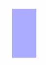
<SYMBOLDEFINITION>
<CANVAS>
<WIDTH>0.5</WIDTH>
<HEIGHT>1</HEIGHT>
<BACKCOLOR>AAAAFF</BACKCOLOR>
<BACKALPHA>1</BACKALPHA>
<BORDERCOLOR>00FF00</BORDERCOLOR>
<BORDERWIDTH>0</BORDERWIDTH>
<BORDERALPHA>0</BORDERALPHA>
</CANVAS>
</SYMBOLDEFINITION>
|
|
Structure of the Annotation Section
This section defines the properties of annotations displayed on the canvas; the following keyword commands are valid for this section:
Keyword Command
|
Description
|
Valid Values
|
WIDTH
|
The width of the annotation (in inches).
|
Any integer or fraction (e.g. 1, 2.5, 3.25 etc.)
|
HEIGHT
|
The height of the annotation (in inches).
|
Any integer or fraction (e.g. 1, 2.5, 3.25 etc.)
|
ANNOTATIONNAME
|
A unique annotation name. If ANNOTATIONTYPE is "ICON", this name specifies the name of the image file to be displayed as an annotation. This image file must exist in the EVA
Netmodeler Graphics Directory.
|
Any alphanumeric string.
|
ANNOTATIONTYPE
|
Specifies whether the annotation is the "Item Name" or an "Icon".
|
Either "ITEMNAME" or "ICON".
|
POS
|
The position of the annotation relative to the top-left corner of the canvas. The notation of this value must conform to the Symbol Definition Point Notation specification defined in
the Symbol Definition Script section above.
|
Two Integers, Fractions or Smalltalk statements delimited by a "@" as described in the Symbol Definition Script section above.
|
Annotation Examples
The following table shows sample annotation XML definitions and how they are rendered in EVA Netmodeler Graphical Modeler
Example XML
|
XML rendered in
EVA Netmodeler Graphical Modeler
|
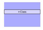
<SYMBOLDEFINITION>
<CANVAS>
<WIDTH>1.5</WIDTH>
<HEIGHT>1</HEIGHT>
<BACKCOLOR>AAAAFF</BACKCOLOR>
<BACKALPHA>1</BACKALPHA>
<BORDERCOLOR>00FF00</BORDERCOLOR>
<BORDERWIDTH>0</BORDERWIDTH>
<BORDERALPHA>0</BORDERALPHA>
</CANVAS>
<ANNOTATION>
<ANNOTATIONNAME>NAME</ANNOTATIONNAME>
<ANNOTATIONTYPE>ITEMNAME</ANNOTATIONTYPE>
<POS>LEFT@(TOP - 20) %2B (HEIGHT //2)</POS>
<HEIGHT>0.12</HEIGHT>
<WIDTH>WIDTH</WIDTH>
<BACKCOLOR>FFFFFF</BACKCOLOR>
<BACKALPHA>0.5</BACKALPHA>
<BORDERCOLOR>000000</BORDERCOLOR>
<BORDERWIDTH>1</BORDERWIDTH>
<BORDERALPHA>1</BORDERALPHA>
</ANNOTATION>
</SYMBOLDEFINITION>
|
|
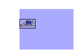
<SYMBOLDEFINITION>
<CANVAS>
<WIDTH>1.5</WIDTH>
<HEIGHT>1</HEIGHT>
<BACKCOLOR>AAAAFF</BACKCOLOR>
<BACKALPHA>1</BACKALPHA>
<BORDERCOLOR>00FF00</BORDERCOLOR>
<BORDERWIDTH>0</BORDERWIDTH>
<BORDERALPHA>0</BORDERALPHA>
</CANVAS>
<ANNOTATION>
<ANNOTATIONNAME>ArchiLogo.gif</ANNOTATIONNAME>
<ANNOTATIONTYPE>ICON</ANNOTATIONTYPE>
<POS>LEFT@(TOP - 20) %2B (HEIGHT //2)</POS>
<HEIGHT>1</HEIGHT>
<WIDTH>WIDTH</WIDTH>
<BACKCOLOR>FFFFFF</BACKCOLOR>
<BACKALPHA>0.5</BACKALPHA>
<BORDERCOLOR>000000</BORDERCOLOR>
<BORDERWIDTH>1</BORDERWIDTH>
<BORDERALPHA>1</BORDERALPHA>
</ANNOTATION>
</SYMBOLDEFINITION>
|
|
Structure of the Pen Definition Section
This section defines the properties of Pen Definitions. The pens defined in this section of the XML will be used in the next section to draw lines on the canvas; the following keyword commands are valid for this section:
Keyword Command
|
Description
|
Valid Values
|
PENNAME
|
A unique pen name.
|
Any alphanumeric string.
|
PENTYPE
|
The type of pen.
|
POLYGON
ELLIPSE
LINE
RECTANGLE
|
PENCOLOR
|
The color of the pen.
|
Web-like HTML RGB value (e.g. 000000 for Black or FFFFFF for White).
|
PENALPHA
|
This command sets the transparency of the pen. A value of 0 means that it is totally transparent; while a value of 1 means that it is totally opaque.
|
Integer 1 or any fraction less than 1, e.g. 0.987
|
PENWEIGHT
|
The thickness of the line that will be drawn by the pen.
|
Any integer greater than or equal to 0
|
PENFILLCOLOR
|
The fill color for the area delimited when the pen draws on the canvas. This setting is only relevant to pen types POLYGON, ELLIPSE and RECTANGLE
|
Web-like HTML RGB value (e.g. 000000 for Black or FFFFFF for White).
|
PENFILLALPHA
|
This command sets the transparency of the PENFILLCOLOR. A value of 0 means that it is totally transparent; while a value of 1 means that it is totally opaque.
|
Integer 1 or any fraction less than 1, e.g. 0.987
|
CORNERSTYLE
|
This command is only relevant to the RECTANGLE type of pen, and indicates whether the corners of the ellipse that is drawn should be rounded or not.
|
"rounded" or "straight"
|
MAJORDASHLENGTH
|
This keyword denotes the length (in pixels) of the major dashes. If it is set, it causes the pen to draw its outline as a dashed line.
|
Any integer greater than or equal to 0
|
MINORDASHLENGTH
|
The length (in pixels) of alternate dashes in the dashed line.
|
Any integer greater than or equal to 0
|
MINORDASHALPHA
|
This command sets the transparency of the minor dashes in the dashed line. A value of 0 means that it is totally transparent; while a value of 1 means that it is totally opaque.
|
Integer 1 or any fraction less than 1, e.g. 0.987
|
MINORDASHCOLOR
|
The color of the minor dashes in the dashed line.
|
Web-like HTML RGB value (e.g. 000000 for Black or FFFFFF for White).
|
DASHSTARTINGOFFSET
|
The purpose of this keyword is unclear, value should be left at 0
|
0
|
DASHMOVEAMOUNT
|
When this keyword is set, the dashes move around the perimeter of the outline drawn by the pen, thereby creating an animated "marquee" effect.
|
Any integer greater than or equal to 0
|
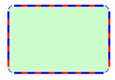
Pen Definition Examples
Although the pen drawing commands are only discussed in the next section, the table below illustrates how different pen
types behave when they are moved from the top left corner of the canvas (i.e. 0@0) to the bottom right (i.e. BOTTOM@RIGHT).
Pen Definition XML
|
XML rendered in
Archi Graphical Modeler
|
<PENDEFINITION>
<PENNAME>RECT</PENNAME>
<PENTYPE>RECTANGLE</PENTYPE>
<PENCOLOR>0000FF</PENCOLOR>
<PENWEIGHT>3</PENWEIGHT>
<PENALPHA>1.0</PENALPHA>
<CORNERSTYLE>rounded</CORNERSTYLE>
<PENFILLCOLOR>00FF00</PENFILLCOLOR>
<PENFILLALPHA>0.2</PENFILLALPHA>
<MAJORDASHLENGTH>10</MAJORDASHLENGTH>
<MINORDASHLENGTH>10</MINORDASHLENGTH>
<MINORDASHCOLOR>FF0000</MINORDASHCOLOR>
<MINORDASHALPHA>0.5</MINORDASHALPHA>
</PENDEFINITION>
|
|
<PENDEFINITION>
<PENNAME>POLLY</PENNAME>
<PENTYPE>POLYGON</PENTYPE>
<PENCOLOR>000000</PENCOLOR>
<PENWEIGHT>1</PENWEIGHT>
<PENALPHA>1</PENALPHA>
<PENFILLCOLOR>FF0000</PENFILLCOLOR>
<PENFILLALPHA>1</PENFILLALPHA> <MAJORDASHLENGTH>10</MAJORDASHLENGTH>
<MINORDASHLENGTH>10</MINORDASHLENGTH>
<MINORDASHCOLOR>FFFFFF</MINORDASHCOLOR <MINORDASHALPHA>0</MINORDASHALPHA>\
<DASHSTARTINGOFFSET>0</DASHSTARTINGOFFSET>
<DASHMOVEAMOUNT>0</DASHMOVEAMOUNT>
</PENDEFINITION>
|
This pen will have no effect, because a polygon must circumscribe an area, which is then filled using PENFILLCOLOR.
|
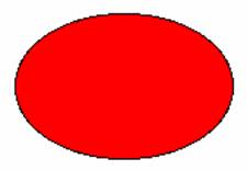
<PENDEFINITION>
<PENNAME>ELLY</PENNAME>
<PENTYPE>ELLIPSE</PENTYPE>
<PENCOLOR>000000</PENCOLOR>
<PENWEIGHT>1</PENWEIGHT>
<PENALPHA>1</PENALPHA>
<PENFILLCOLOR>FF0000</PENFILLCOLOR>
<PENFILLALPHA>1</PENFILLALPHA> <MAJORDASHLENGTH>10</MAJORDASHLENGTH>
<MINORDASHLENGTH>10</MINORDASHLENGTH>
<MINORDASHCOLOR>FFFFFF</MINORDASHCOLOR>
<MINORDASHALPHA>0</MINORDASHALPHA>
<DASHSTARTINGOFFSET>0</DASHSTARTINGOFFSET>
<DASHMOVEAMOUNT>0</DASHMOVEAMOUNT>
</PENDEFINITION>
|
|
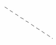
<PENDEFINITION>
<PENNAME>LINEY</PENNAME>
<PENTYPE>LINE</PENTYPE>
<PENCOLOR>000000</PENCOLOR>
<PENWEIGHT>1</PENWEIGHT>
<PENALPHA>1</PENALPHA>
<PENFILLCOLOR>FF0000</PENFILLCOLOR>
<PENFILLALPHA>1</PENFILLALPHA>
<MAJORDASHLENGTH>10</MAJORDASHLENGTH>
<MINORDASHLENGTH>10</MINORDASHLENGTH>
<MINORDASHCOLOR>FFFFFF</MINORDASHCOLOR>
<MINORDASHALPHA>0</MINORDASHALPHA>
<DASHSTARTINGOFFSET>0</DASHSTARTINGOFFSET> <DASHMOVEAMOUNT>0</DASHMOVEAMOUNT>
</PENDEFINITION>
|
|
Structure of the Pen Command Section
In this section, the Pen Command XML is described. Pen commands are the parts of the XML that do the actual drawing on the canvas. The following pen commands are available;
Keyword Command
|
Description
|
Valid Values
|
PENSTATE
|
This sets the state of the Current Pen to be either "UP" or "DOWN". If a pen is "DOWN", a move command will cause it to draw on the canvas. If the pen state is "UP", a move
command will only change the Current Position of the pen, but nothing will be drawn on the canvas.
|
UP
DOWN
|
USEPEN
|
This command sets the Current Pen. All subsequent commands will be executed using this pen until another pen is set as the Current Pen by the USEPEN command
|
The name of a Pen as set in the Pen Definitions part of the XML
|
PENMOVETO
|
This command moves the pen to an absolute position on the canvas. If the pen is "DOWN" and the PENTYPE is LINE, a line will be drawn from the current pen position to the new
position.
|
Two Integers, Fractions or Smalltalk statements delimited by a "@" as described in section 1.2.
|
PENMOVEREL
|
This command moves the pen to position relative to the current pen position.
|
Two Integers, Fractions or Smalltalk statements delimited by a "@" as described in section 1.2.
|
Pen Command Examples
The following table shows how Pen Commands are executed. In this example, two pens are defined, the first is of PENTYPE=LINE and has a NAME=LINE, while the second is of PENTYPE=ELLIPSE and has a NAME=ELLIPSE.
Keyword Command
|
Description
|
XML rendered in
Archi Graphical Modeler
|
<USEPEN>
LINE
</USEPEN>
|
Tell Archi Graphical Modeler to set the current pen definition to a pen called "LINE"
|
Nothing is rendered as a result of this command, but the Current Pen is set to "LINE"
|
<PENSTATE>
UP
</PENSTATE>
|
Set the state of the current pen to "UP"
|
Nothing is rendered as a result of this command
|
<PENMOVETO>
LEFT %2B (WIDTH // 2) @ TOP %2B (HEIGHT // 2)
</PENMOVETO>
|
Move the current pen to the centre of the canvas
|
Because the PENSTATE is "UP", nothing is drawn on the canvas.
|
<PENSTATE>
DOWN
</PENSTATE>
|
Set the state of the current pen to "DOWN"
|
Nothing is rendered as a result of this command
|
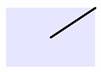
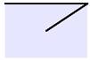
<PENMOVEREL>
WIDTH // 2 @ (-1) * HEIGHT // 2
</PENMOVEREL>
|
Move the current pen to a position upwards and to the right relative to its current position.
|
|
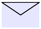
<PENMOVETO>
LEFT@TOP
</PENMOVETO>
|
Move the current pen to the top left corner of he canvas
|
|
<PENMOVETO>
LEFT %2B (WIDTH // 2) @ TOP %2B (HEIGHT // 2)
</PENMOVETO>
|
Move the current pen to the centre of the canvas
|
|
<USEPEN>
ELLIPSE
</USEPEN>
|
Tell Archi Graphical Modeler to set the current pen definition to a pen called "ELLIPSE"
|
Nothing is rendered as a result of this command, but the Current Pen is set to "ELLIPSE"
|
<PENSTATE>
UP
</PENSTATE>
|
Set the state of the current pen to "UP"
|
Nothing is rendered as a result of this command
|
<PENMOVETO>
LEFT @ TOP %2B (HEIGHT // 2)
</PENMOVETO>
|
Move the current pen to the middle left of the canvas
|
Because the PENSTATE is "UP", nothing is drawn on the canvas.
|
<PENSTATE>
DOWN
</PENSTATE>
|
Set the state of the current pen to "DOWN"
|
Nothing is rendered as a result of this command
|
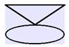
<PENMOVEREL>
WIDTH @ HEIGHT // 2
</PENMOVEREL>
|
Move the current pen to a position downwards and to the right relative to its current position.
|
|
|